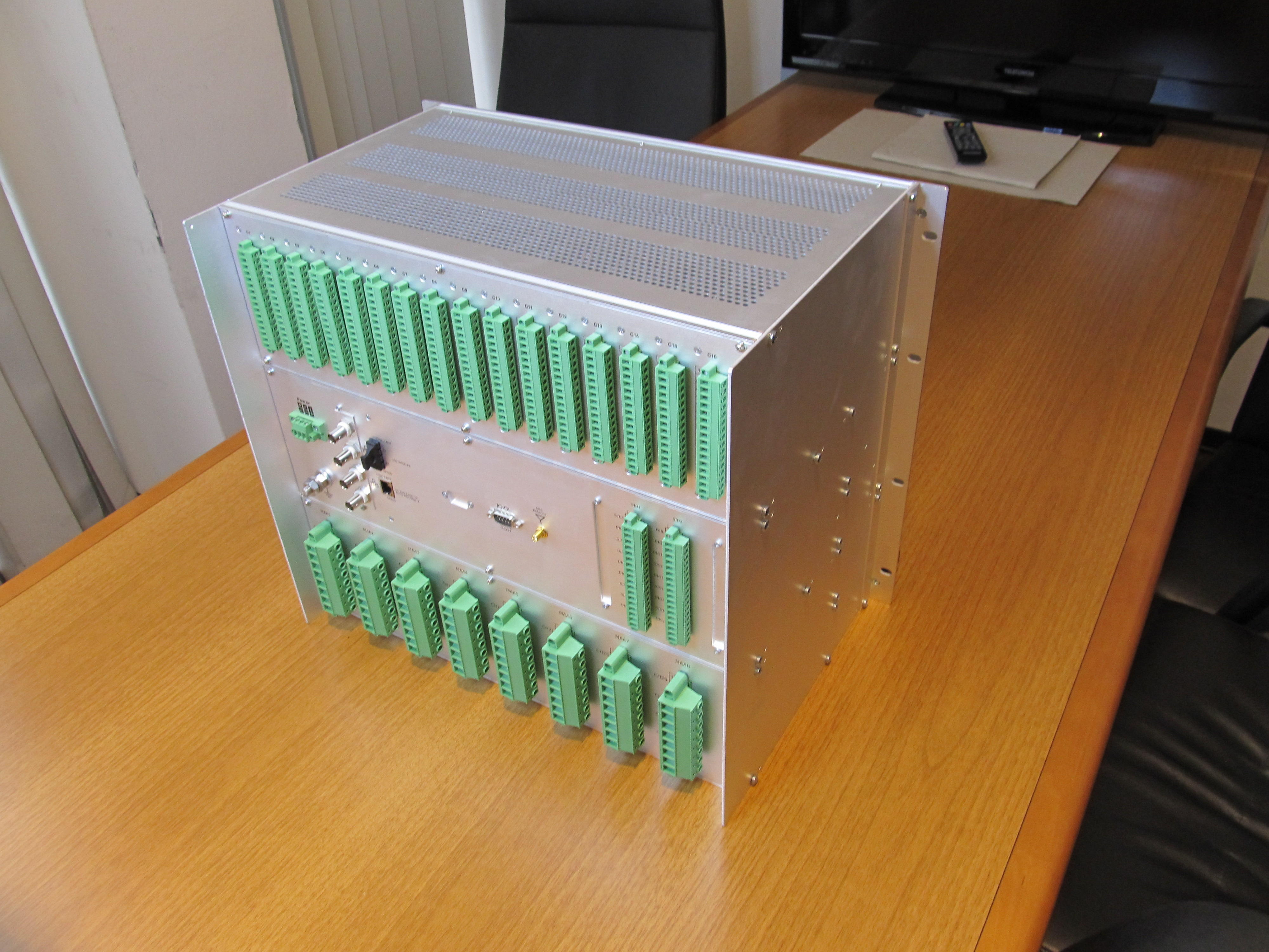
General
Standard
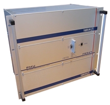
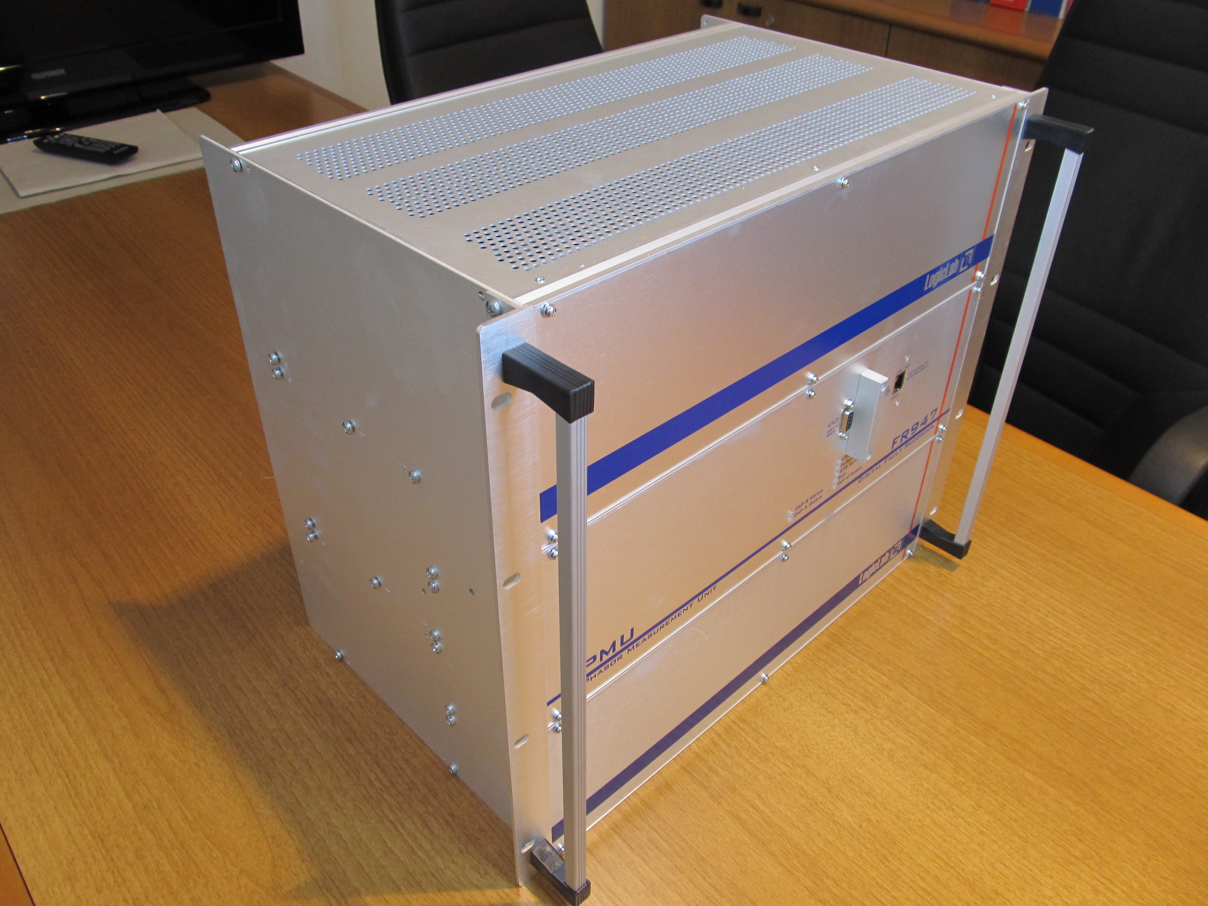
19” rack mount
Height / Width / Depth: 6U or 9U / 19” / 31 to 40 cm
Operating temperature range: -10 ÷ +55°C
Storage temperature range: -40 ÷ +85°C
Relative Humidity: <95 %
Atmospheric pressure: 70 ÷ 106 kPa
Intrusion Protection: IP20
System frequency: 50/60Hz
Power supply
Power
supply voltage (Vaux):
Universal AC/DC power supply
AC 88-264V 48-62Hz
DC 88-350V
Maximum power consumption: 40W
Voltage dips and short interruption
Insensitive to 100% of Vaux for 50 ms (min)
Insensitive to 50% of Vaux for 100ms (min)
Analog
inputs
Hardware features
4 to 32
analog inputs
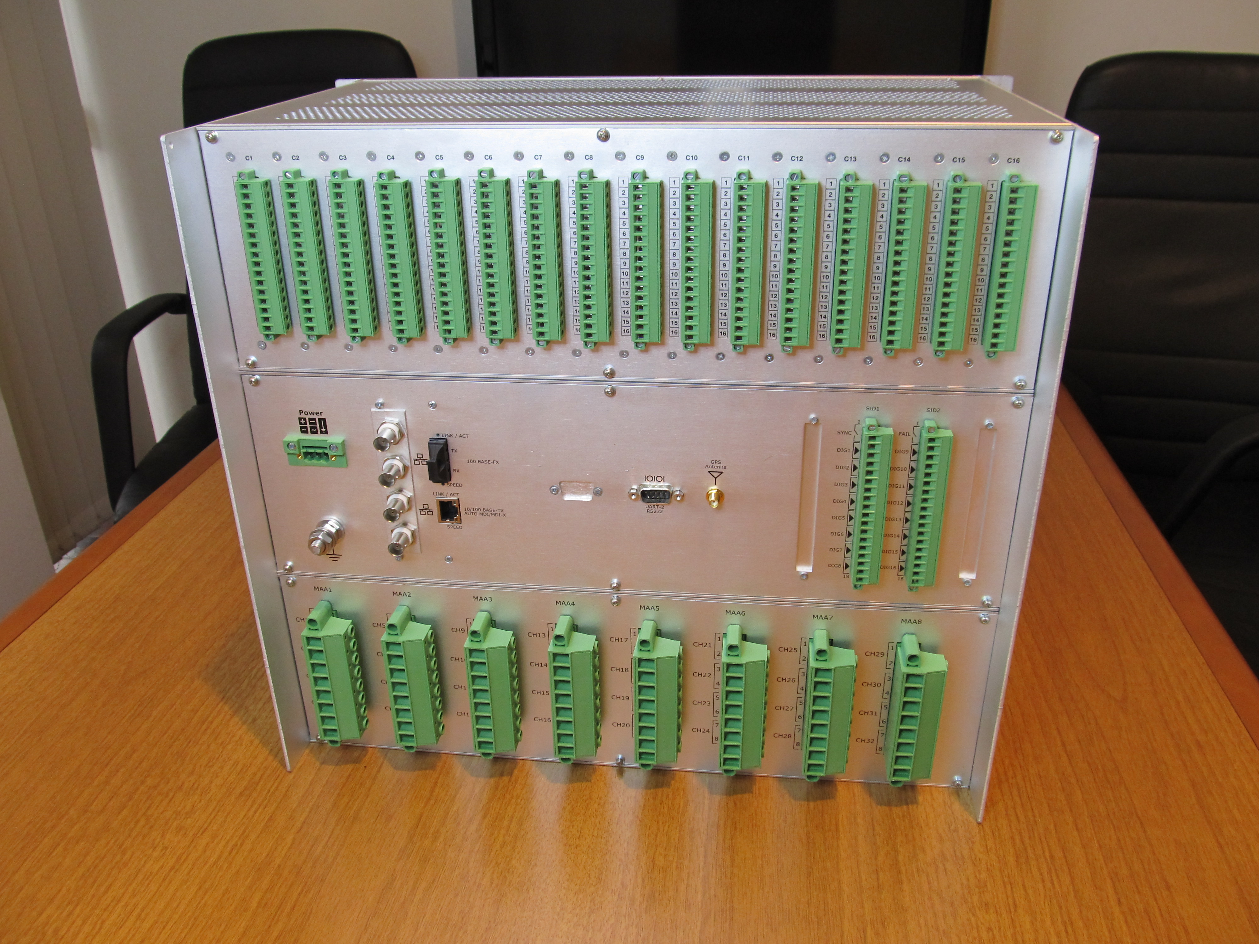
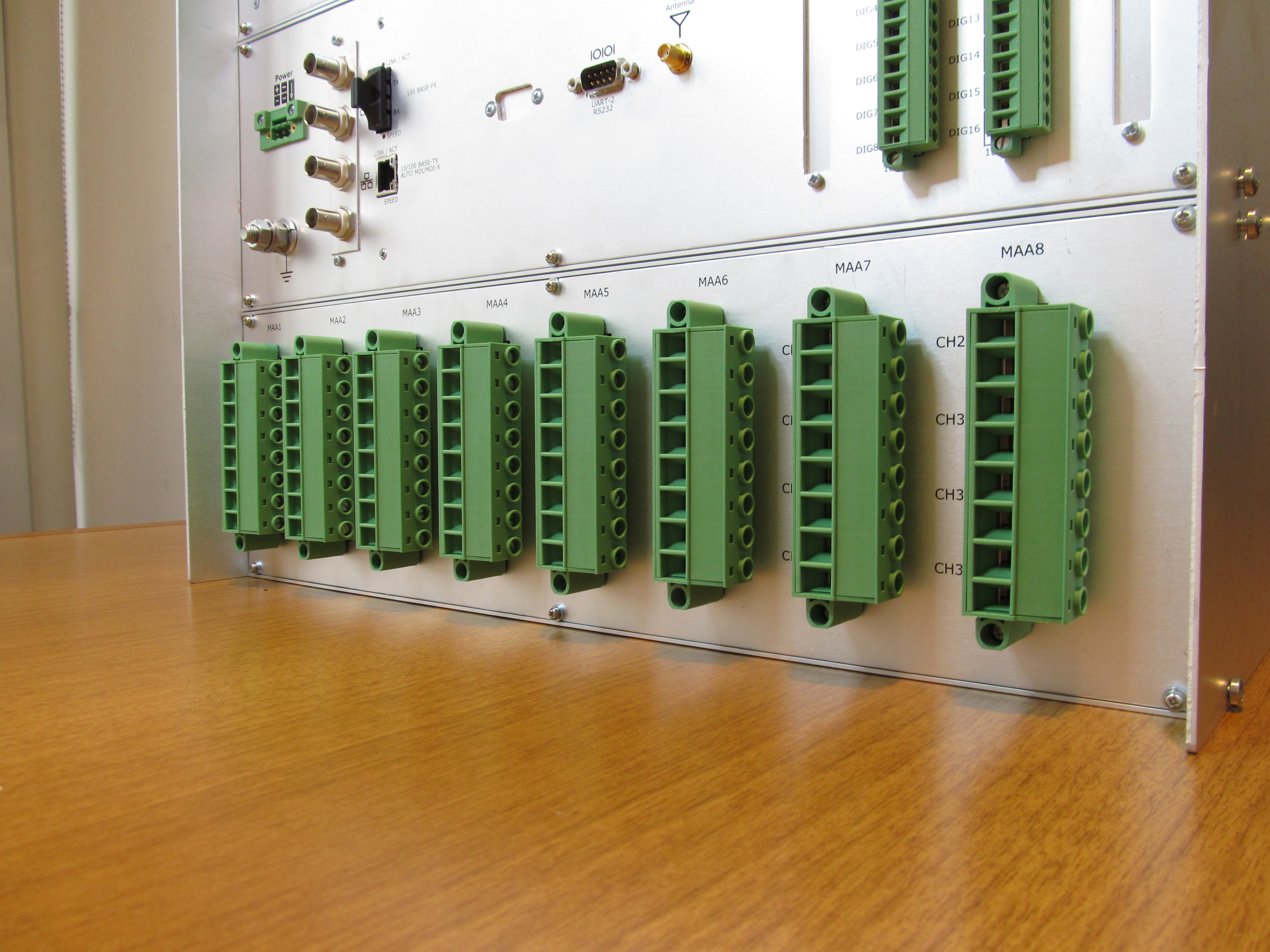
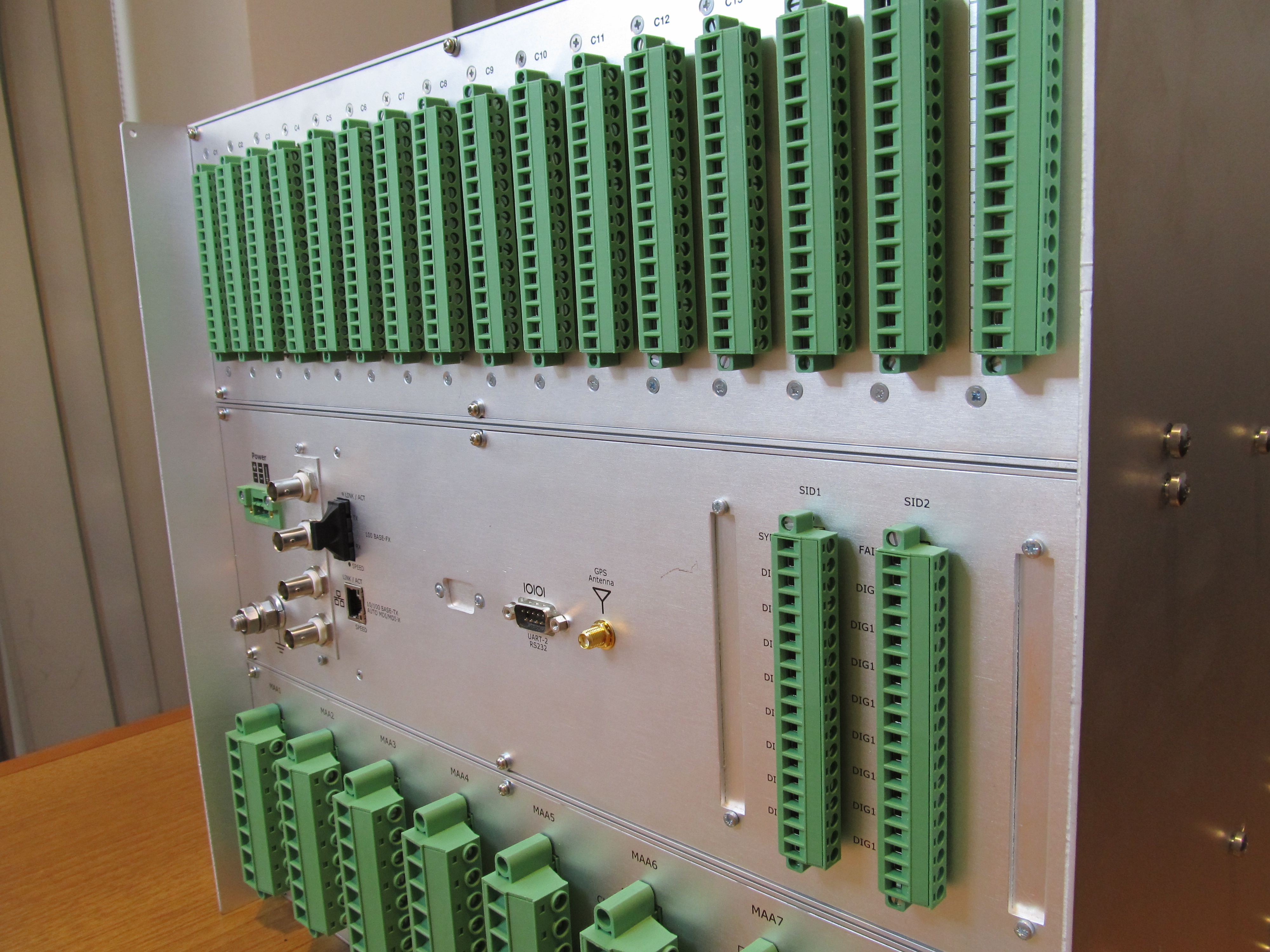
Three different connections:
Screw fixing removable connector (standard)
Spring-clamp connectors for high reliability wiring
Barrier strips connectors for cables with ring terminals
Analog to digital conversion: 24 bit
One ADC per analog input
Sigma-Delta ADC with sampling frequency up to 5.7 MHz
PGA Amplifier for up to 5 different measuring range
Channel typology (voltage/current) in factory configurable
Dielectric strength: 3000V DC (1 min)
Configurable sample rate (fs):
up to 224 sample/period @16bit
up to 144 sample/period @24bit
Bandwidth (-3 dB): DC (0 Hz) ÷ 0.49·fs
Flat bandwidth(±0,005 dB): DC (0 Hz) ÷ 0.45·fs
Stop band attenuation: >100 dB (f>0.55·fs)
Resolution: 16 or 24 bit @1
SNR (Signal to noise ratio): >92 dB
Cross-over: < -92 dB
Software features
Feeder (4
current + 4 voltage inputs) configuration
Up to 7 different feeders
Primary/secondary transformer side representation
CT/CVT transformer ratio management
Software signal reverse (±180° angle)
User configurable Gain and Phase correction
Up to 5 different full scale values for each channel
Analog input full scale singly configurable by software setup
Full-scale values in factory configurable up to Max Full-scale
Current analog inputs
Max
Full-scale: up to 150Arms (Standard)
up to 400Arms (-C Option)
Standard full-scales (FSI): 15A, 30A, 50A, 150A, 400A
Low amplitude DC input on client demand (i.e. ±20 mADC)
Accuracy guaranteed range: 0,01∙In ÷ FSI
RMS Accuracy (Standard): (0.1% of Reading + 0.005%*FSI)
RMS Accuracy (-C Option): (0.1% of Reading + 0.01%*FSI)
Accuracy (Low DC input): (0.01% of Reading + 0.0005%*FSI)
Overload capability:
40A permanently
500A (1 second)
Input impedance:
3 mohm (Standard)
1,5 mohm (-C Option)
Power dissipation max: 37,5 mVA @ In
Voltage analog
inputs
Max
Full-scale: 700Vrms
Standard full-scales (FSV): 100V, 200V, 700V
Low amplitude DC input on client demand (i.e. ±10VDC)
Accuracy guaranteed range:
50mVrms ÷ 100Vrms @ FSV=100Vrms
100mVrms ÷ 200Vrms @ FSV=200Vrms
0,35Vrms ÷ 700Vrms @ FSV=700Vrms
RMS Accuracy (Standard): (0.1% of Reading + 0.005%*FSV)
Accuracy (Low DC input): (0.01%of Reading + 0.0005%*FSV)
Input impedance: 1 Mohm
Power dissipation: 160 mVA @ 400V
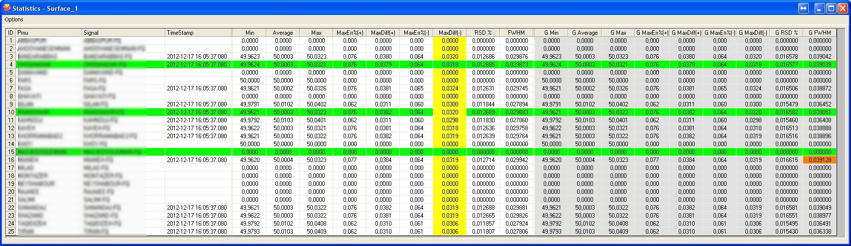
Measure calculated and accuracy
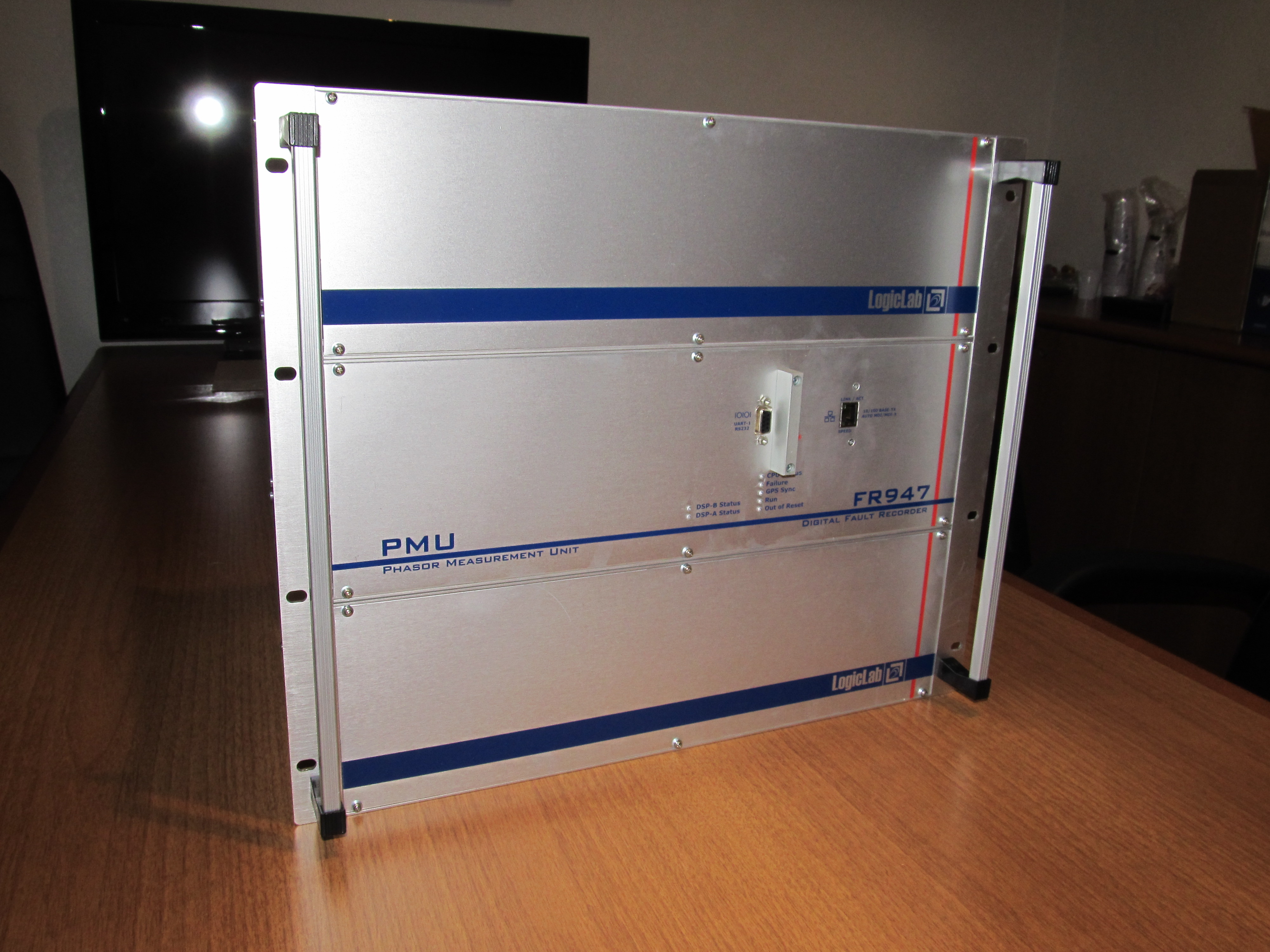
FR947
calculates each half period up to 234 different measures:
RMS value* (0.1%)
50/60 Hz RMS value* (0.1%)
Absolute Phase* (±0.01°)
Frequency** (±0.3 mHz)
ROCOF** (±1 mHz/s)
THD* (±0.5%)
Positive, negative and zero sequences RMS** (0.4%)
Positive, negative and zero sequences Phase** (±0.1°)
Active, reactive and apparent powers*** (0.4%)
Power factor*** (±0.005)
Partial and total Energy*** (0.5%)
* up to 32 measures (one for each analog
inputs)
** up to 8 measures (one for each group of 4 voltage or 4 current inputs
** up to 7 measures (one for each feeder)
Digital inputs
Up to 128
single channel isolated inputs x2
In factory configurable rated voltage
Available rated voltage (Vi): 24V, 48V, 110V, 220V
AC input capability on request
Dielectric strength: 3000V DC (1 min)
Thresholds (typ):
High - 60% Vi
Low - 40% Vi
Maximum voltage (max): 1.2*Vi
Time resolution: 1 ms
Anti-bounce filter
Alarm
outputs
Alarms
board with 8 relays 22
Relay Technical Data
Rated carry current: 12A
Maximum switching voltage DC: 300V
Maximum switching voltage AC: 440V
Maximum switching current : 12A
Maximum switching power: 3000VA
Contact resistance (max): 100 mohm
Maximum operating frequency: 18000 operation/hour
Minimum endurance: 20•10^6 operations
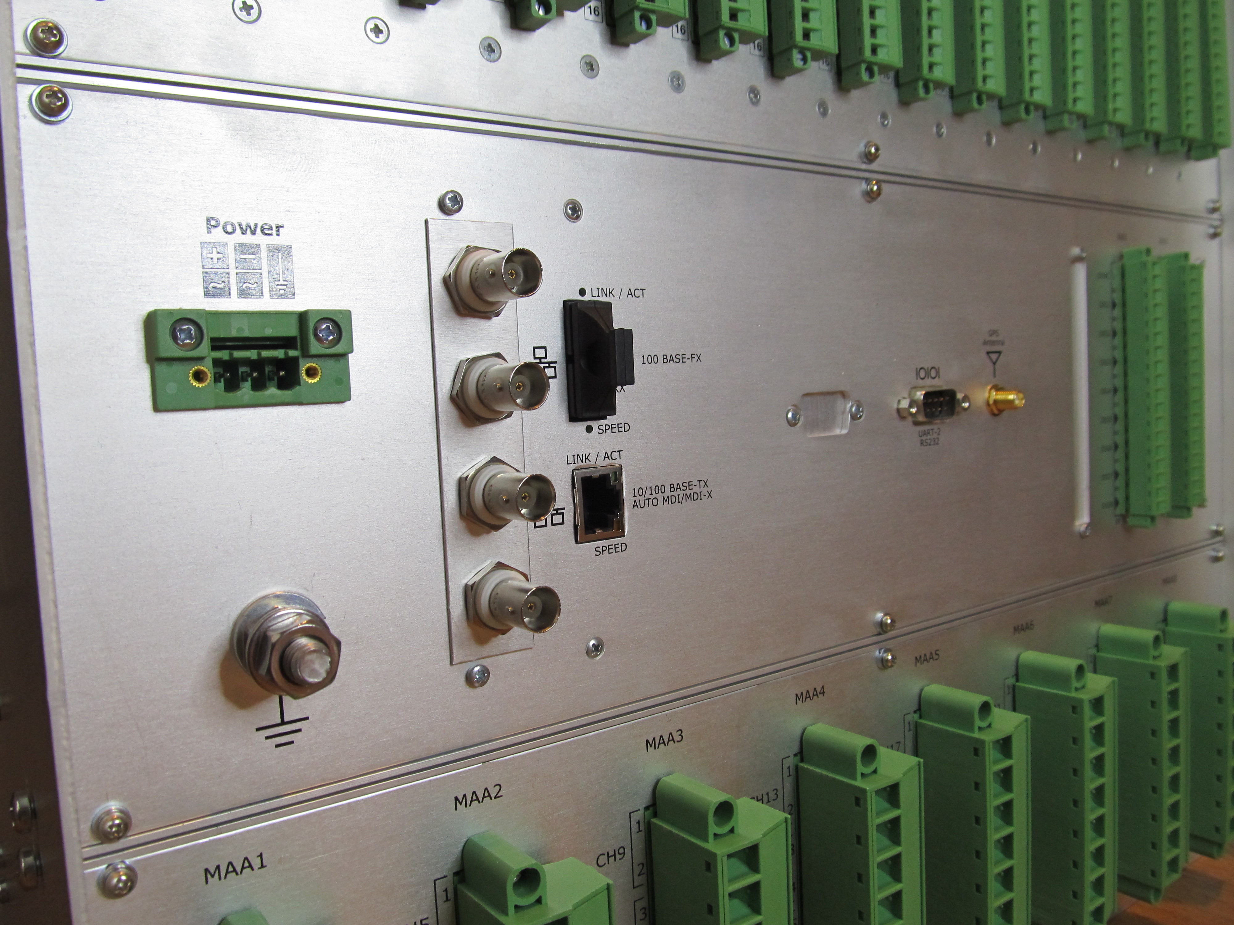
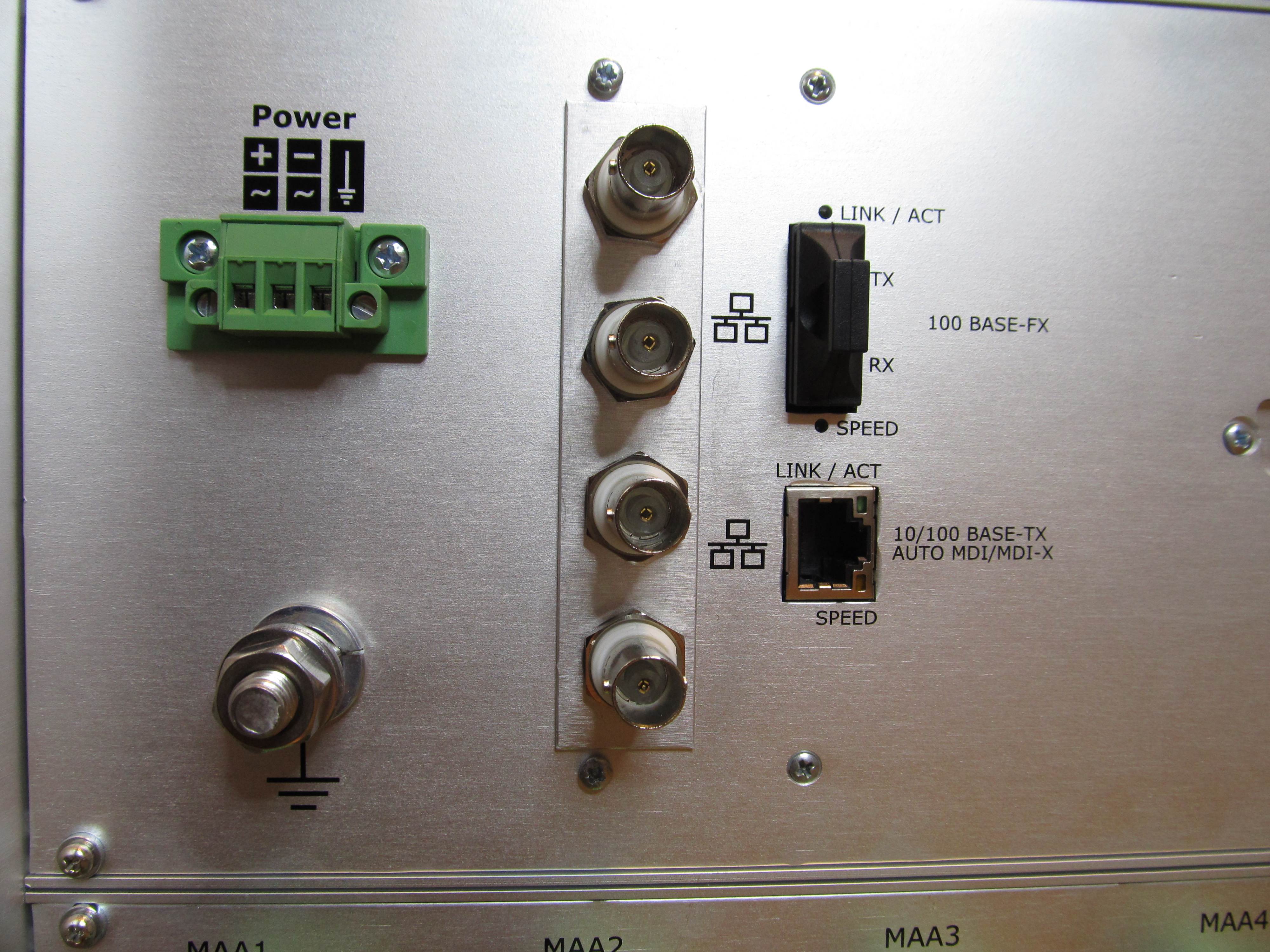
Communication and interfaces
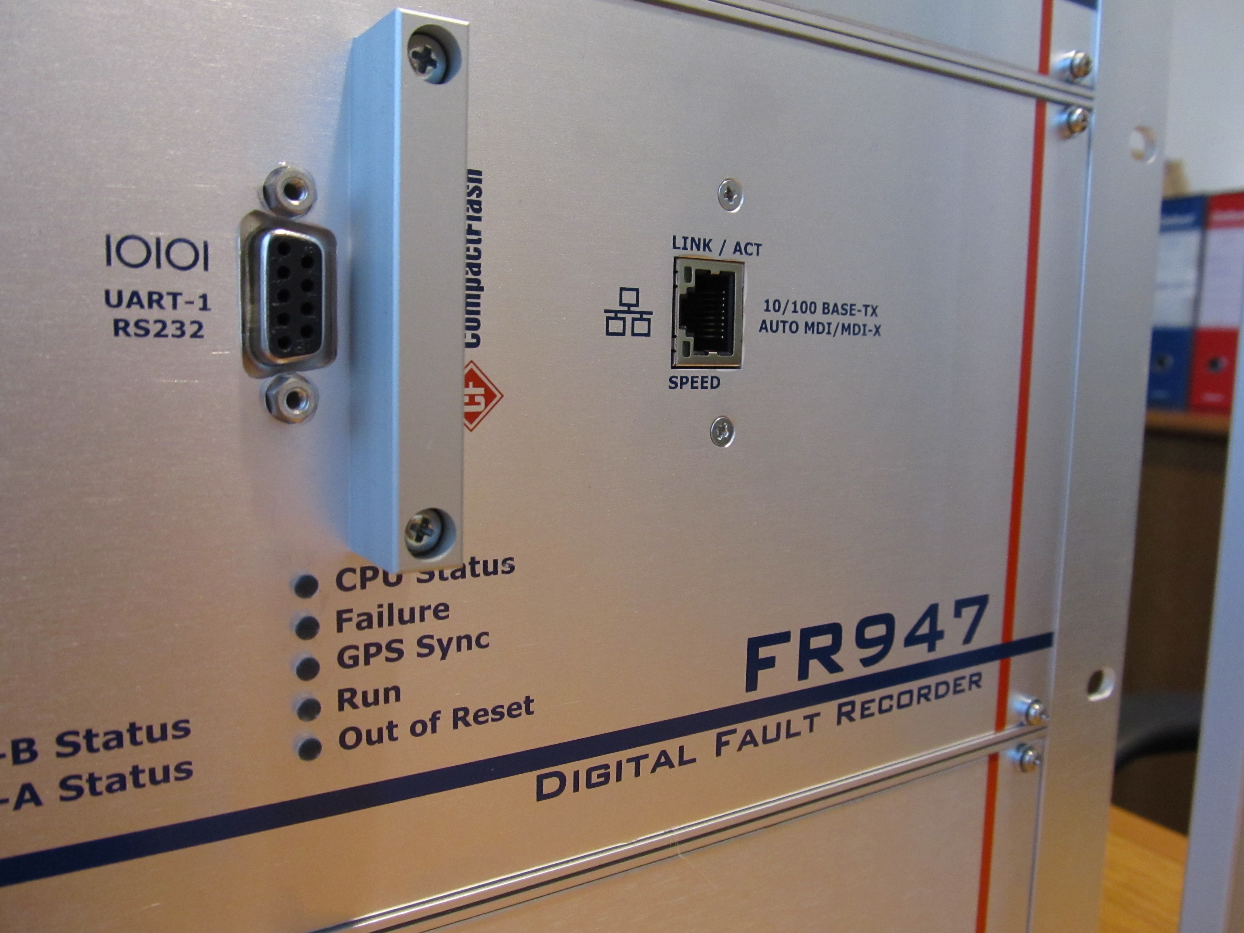
Three
Ethernet ports:
Configurable as node of a net LAN/WAN
Front 10/100 BASE-TX with auto MDI/MDI-X
Connection: RJ45 8/8
Isolation: 1500VRMS
Rear 10/100 BASE-TX with auto MDI/MDI-X x
Connection: RJ45 8/8
Isolation: 1500VRMS
Rear 100BASE-FX (Fiber optic with SC connector) x
Transmitter Centre Wavelength: 850 nm
Operating Receiver Centre Wavelength: 770nm÷860nm
Sensitivity: -24 dBm
Available adapters for ST and LC connectors
2 RS232
Front RS232
Plug Type: DB9
Baud rate (Fixed): 19200 bit/s
Isolation: 2500VRMS
Typical use: Local communication
Back RS232
Plug Type: DB9
Baud rate: 9600 bit/s to 115200 bit/s
Isolation: NO
Typical use: GSM/Dial-up modem (modem not included)
RS485 on client demand
SMA connector for satellite antenna
Multiple simultaneous connections over serial and Ethernet
HMI with display and keypad
Alphanumeric display 4 rows x 20 columns
16 LEDs: 2 red for alarms and 14 green for information
Full phone-like keypad and four arrow keys
Isolated and shielded membrane
Architecture
Multiprocessor architecture: 32 bit CPU + dual 3.6 GFLOPS DSPs
Real Time Operating System RTEMS
256 Mbyte DDR RAM + 128 MByte SDRAM
Up to 32 Gbyte Compact Flash card for storage data
Compact Flash partitioning utility with FIFO capability
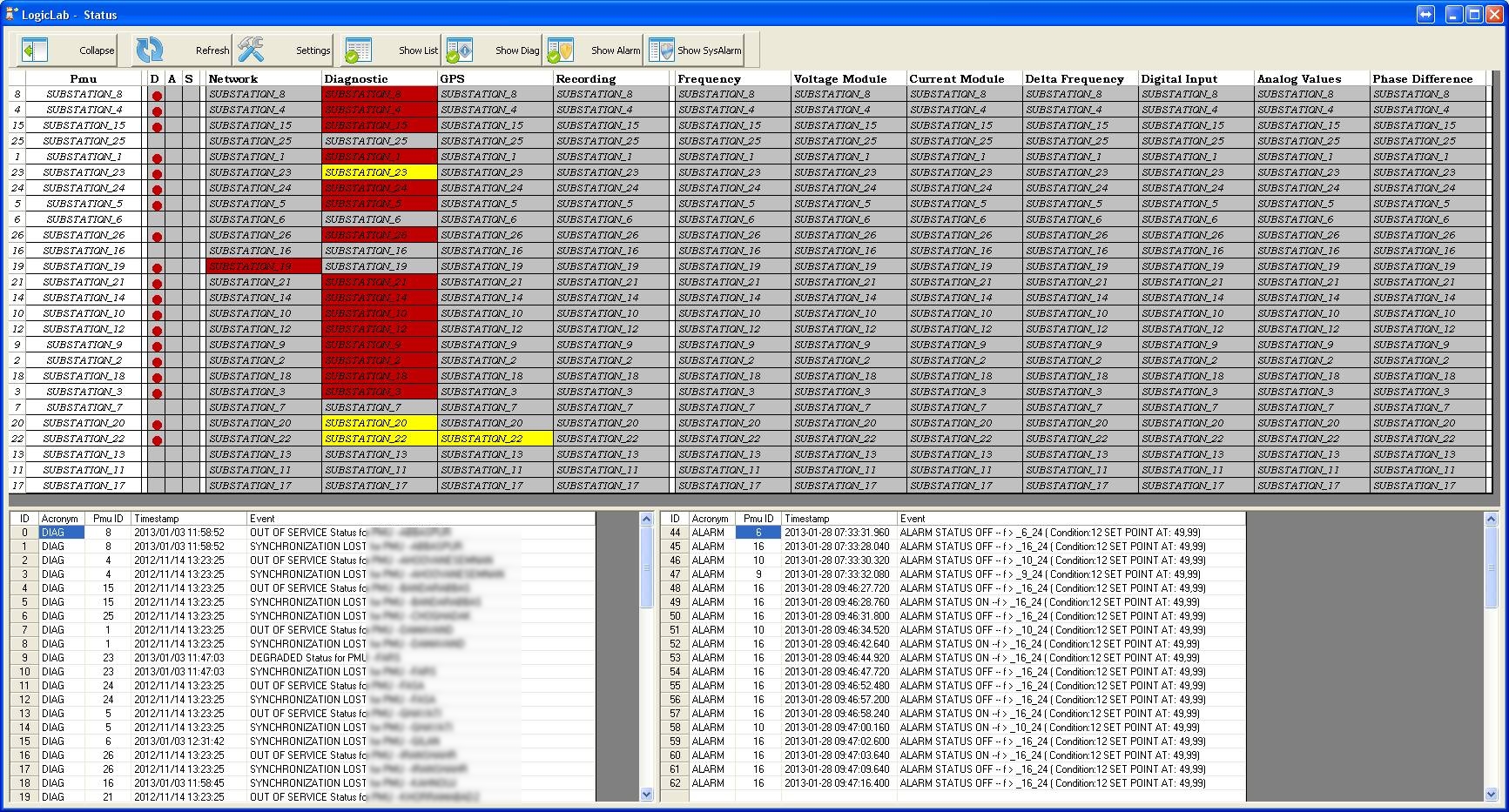
Self
diagnostic with Watch Dog capability
User/password access with 5 different level of security (optional)
Time
synchronization
Integrated GPS unit
Channels: 22 tracking / 66 acquisition
Sensitivity:
Acquisition (cold): -148dBm
Re-Acquisition: -160dBm
Tracking: -165dBm
1PPS accuracy: ±50ns
Standard active GPS antenna with 20m RF cable SMA connector @
Optional active GPS antenna with up to 100m RF cable SMA connector 2
IRIG-B synchronization board:
I/O isolation: 2500VRMS
Available connections:
AM IRIG-B IN Modulated IRIG-B input
IRIG-B / 1PPS IN (Mux) Unmodulated IRIG-B input
1PPS input
IRIG-B OUT Unmodulated IRIG-B output
1PPS OUT 1PPS output
Voltage levels:
AM IRIG-B IN Max 12VPP
IRIG-B / 1PPS IN (Mux) 5V TTL
IRIG-B OUT 5V TTL
1PPS OUT 5V TTL
1PPS IN to 1PPS OUT max propagation delay: <50ns
Unmodulated IRIG-B IN frame to 1PPS out delay: <50ns
Modulated AM IRIG-B IN frame to 1PPS out delay: <20µs
1PPS signal:
Normally low
High for 8ms
Supported IRIG-B Format
Default configuration: IRIG-B006
Available formats: IRIG-B00# / IRIG-B12#
SNTP synchronization
Internal clock backup with accuracy drift better than 5ppm
Synchronization source priority definition with automatic restore
Transient Analog Recording (TAR)
Transient analog waveforms and digital status
recording
Three timers user configurable
Pre-trigger time: 100 ms ÷ 5 s
Fault time: 100 ms ÷ 60 s
Post fault time: 100 ms ÷ 5 s
Re-triggering during recording time available
Record time out (max): 150 s
Trigger on analog thresholds (Max, Min, Rate-Of-Change):
RMS
Positive, Negative and Zero sequence (I1,2,0,U1,2,0)
Power: P, Q, S, cos φ
Frequency
THD
Trigger on digital edge (falling edge, rising edge, both edges)
Software trigger
Cross triggering capability for FR947 system
Transient Measures Recording (TMR)
Disturbance slow recording
Three timers and data period configurable
Pre-trigger time: 100 ms ÷ 60 s
Fault time: 100 ms ÷ 7200 s
Post fault time: 100 ms ÷ 5 s
Data period: 10 ms ÷ 1 s
Configurable stored data packet (Measures and feeders)
Trigger on TAR
Slow Measure Recording (SMR)
Disturbance and trend
slow recording
Four
different configurable SMR
Single parameter set for each SMR (4 different configuration available)
Fault timer and data period configurable
Fault time: up to 365 d : 23 h : 59 m
Data period: 10 ms ÷ 600 s
Configurable stored data packet (Measures and feeders)
Configurable intermediate backup
Configurable measure stored: average/instantaneous
Configurable as continuous slow recording
Trigger on analog thresholds (Max, in, Rate-Of-Change):
RMS
Positive, Negative and Zero sequence (I1,2,0,U1,2,0)
Power: P, Q, S, cos φ
Frequency
THD
Trigger on digital edge (falling edge, rising edge, both edges)
Time scheduled trigger
Software trigger
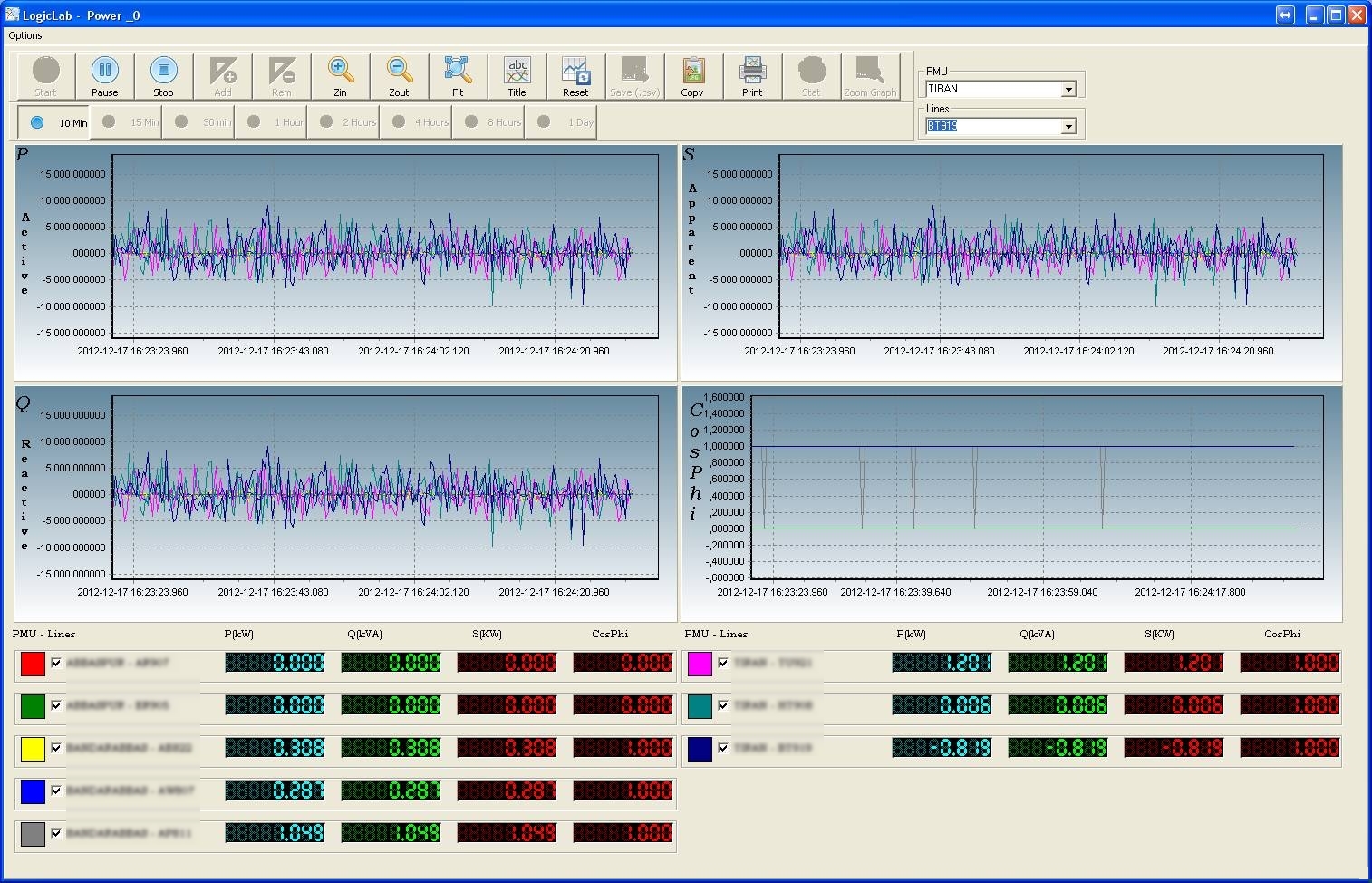
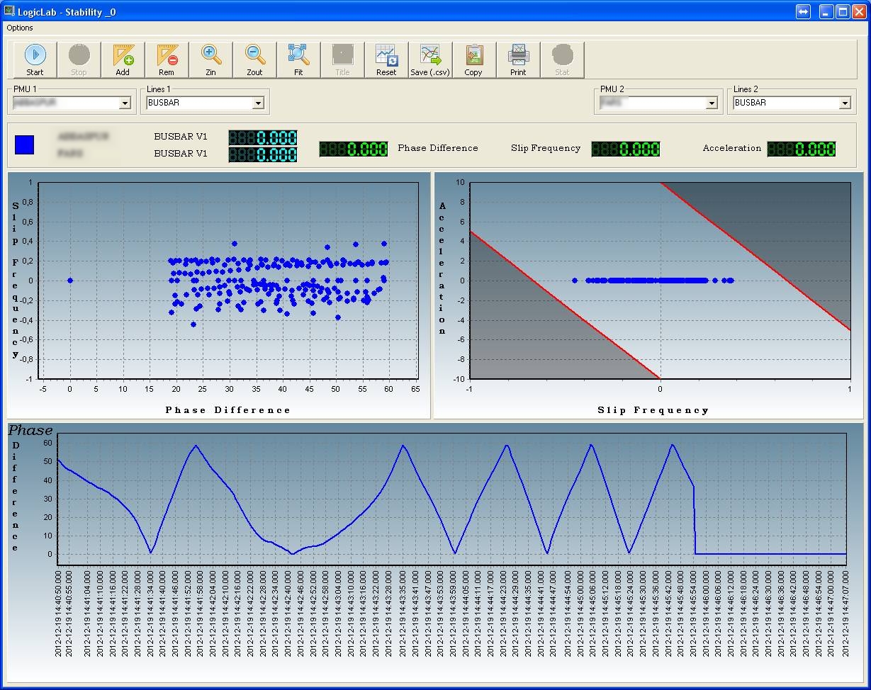
Synchrophasor (PMU)
Compliant
to IEEE C37.118
Up to 32 synchrophasors (all analog inputs)
Total vector error: <1%
Data transfer rate (frame/s):
10,25,50 @50Hz
10,12,15,20,30,60 @60Hz
Synchronization error between different channels: <300ns
Maximum error on synchronization time: <4µs
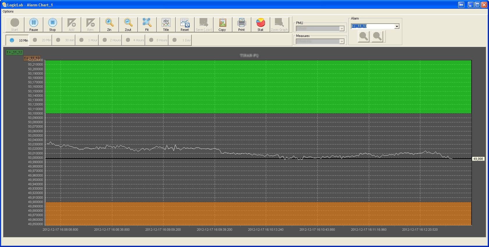
Power
Quality
Voltage
and frequency profiles
Voltage dips and surges
Harmonic components
Flicker analysis
Voltage and Current imbalance
Standards and specifications compliance:
IEC 61000 - 4 - 7
IEC 61000 - 4 - 15
IEC 61000 - 4 - 30
Event
Recorder
Sequence
of event recorder for disturbance events and diagnostic
Dual event logs (disturbance and diagnostic)
Each log is capable to collect up to 1000 events
Time tag with millisecond accuracy
Standards and specifications compliance
IEC 61000
– 4 – 2 (Level 3)
IEC 61000 – 4 – 3 (Level 3)
IEC 61000 – 4 – 4 (Level 3)
IEC 61000 – 4 – 5 (Level 4)
IEC 61000 – 4 – 6 (Level 3)
IEC 61000 – 4 – 8 (Level 5)
IEC 61000 – 4 – 10 (Level 3)
IEC 61000 – 4 – 12 (Level 3)
IEC 61000 – 4 – 16 (Level 4)
IEC 61000 – 4 – 17 (Level 3)
IEC 61000 – 4 – 29 (Level 3)
IEC 60529 (IP20)
COMTRADE standard IEEE Std C37.111
Naming Time Sequenced Data Files compliant to IEEE C37.232-2007 2
Optional protocols:
Communication networks and systems in substations IEC 61850 2
Telecontrol equipment and systems protocol IEC 60870-5-104 2
|