|
|
||||||||||||
 |
||||||||||||
|
|
||||||||||||
|
||||||||||||
|
Digital Fault Recorders Testing Devices Protection Relays Monitoring Devices
|
FR947 |
|
||||||||||
Digital fault and event recorder
Check the more advanced Digital Fault Recorder FR947-EX/PMU |
||||||||||||
|
|
|
ENEL Device certified |
||||||||||
Digital Fault Recorder introduction |
|
|||||||||||
|
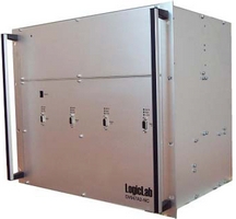
FR947 is a family of digital fault recorder. This is the base version of the DFR family, LogicLab portfolio is completed with EX version (Extended Signal Processor capability) and PMU version (Phasor Measurement Unit). LogicLab has developed a high-performance device, achieving a fault recorder that has no comparison with the other ones on the market. With up to 32 analog inputs (voltage and current) noise-free and 128 digital inputs, it provides great potential with high levels of precision and accuracy. Each channel (analog or digital) is isolated from all the other channels, power supply and ground. The device is intended for power distribution medium and high voltage substations, and it is used to record currents, voltages and digitals input following the occurrence of a trigger condition which can be set both as analog or digital inputs, as you please. User can set trigger on analog inputs using threshold (Max, Min or rate) on RMS value, fundamental RMS value, THD, positive sequence, negative sequence, zero sequence, active and reactive power, frequency. All trigger conditions (analog and digital) can be enabled and used in logical OR with other triggers or used in logical AND equations. Digital fault recorder FR947 uses the GPS signal for time synchronization and events timestamp. This feature provides a time value with resolution of ms and a µs accuracy. GPS receiver is integrated into the device and fault recorder is equipped with an external antenna. Other synchronization source, as NTP server or IRIG-B, are available. Equipped with an ethernet 10/100 BASE-TX (100 BASE-FX on demand) and RS232 connection, the user, with a common PC, can obtain a fully parameterization, remote control over VPN network, and remote recording download. FR947 is equipped with an internal flash memory and, with automatic download, the device memory capability to the computer mass storage device. FR947 is equipped with two user-friendly software: 1) SpyFR947 for a complete device management, providing realtime tools, recording management and parameterization; 2) LogOscillo: a complete set of tools for an effective, powerful and precise recording analysis. LogicLab can supply tailored multi-device system based customer specification with multi-device and high performance industrial PC, complete of rack and cabling on terminal block based on to meet large demands of analog and digital inputs. FR947 Power, precision and reliability.
Check the more advanced Digital Fault Recorder FR947-EX/PMU
|
||||||||||||
Digital Fault Recorder Documentation |
|
|||||||||||
|
If the English version is not available, contact us and we will provide the document that you have requested.
To download from
the website the User Guide it is necessary to have a user name and
password. |
||||||||||||
Digital Fault Recorder Data Sheet |
|
|||||||||||
|
Power supply Power supply voltage: 110V DC ± 20% Nominal power: 40W AC version available on client demand Different power supply voltage available on client demand
Dimensions and environmental specification Height / Width / Depth: 9U / 19” / 31cm Temperature range: -10 ÷ 55 ºC Temperature range (Absolute maximum rating): -15 ÷ 70 ºC Storage temperature: -40 ÷ 85 ºC Relative Humidity: £ 95 % Atmospheric pressure: 70 ÷ 106 kPa
Analog inputs noise-free isolated input Dielectric strength: 3000V DC (1 min - 100% tested) Sample rate: 14,4 KHz Bandwidth (-3 dB): DC (0 Hz) ÷ 3,5 KHz Flat bandwidth(±0,005 dB): DC (0 Hz) ÷ 3,25 KHz Stop band attenuation: >100 dB Different configuration of current/voltage analog input Available options: 32V, 28V+4I, 24V+8I, 20V+12I, 16V+16I, 12V+20I, 8V+24I, 4V+28I, 32I Under-equipped configuration for cost-saving solution
Current analog inputs Rated current (In): 1Arms / 5Arms Full-scale range: 50 Arms / 150 Arms / 300 Arms Accuracy guaranteed range: 0,01∙In ÷ 30∙In Rated current setup by software command Accuracy: <0,1% ± 1 mA Permanent overload: 40A Maximum overload: 300 A (1 second) Input impedance: 1,5 mohm (purely resistive) Power dissipation (1A): 0,005 VA @ In Power dissipation (5A): 0,05 mVA @ In Resolution (ENOB): 16 bit noise-free SNR (Signal to noise ratio): 92 dB Cross-over: < -92 dB
Voltage analog inputs Full-scale range: 100Vrms / 200Vrms / 700Vrms Accuracy guaranteed range: 14mVrms ÷ 100Vrms @ Pn=100Vrms 28mVrms ÷ 200Vrms @ Pn=200Vrms 0,1Vrms ÷ 700Vrms @ Pn=700Vrms Rated voltage setup by software command Accuracy: <0,1% ± 5 mV Input impedance: 1 Mohm (purely resistive) Power dissipation: 0,5 VA @ 400V Resolution (ENOB): 16 bit noise-free SNR (Signal to noise ratio): 92 dB Cross-over: <-86 dB
Digital input 128 isolated input Dielectric strength 3000V DC (1 min - 100% tested) Threshold (min): 18V Maximum voltage (max): 150V Time resolution: 1 ms
Communication Ethernet 10/100 BASE-TX Configurable as knot of a net LAN/WAN 1 RS232 front side (19.200 baud fixed) 1 RS232 back side (up to 115.200 baud) Remote connection with analog modem (not included) Isolated communication port (Ethernet: 1500Vrms – Serials: 2500 Vrms) GPS satellite connection HMI with display and keypad (optional) IRIG-B synchronization (optional)
Signal outputs Out of order relay Recording in progress relay -20mA/20mA current output with configurable range (optional) Additional alarms with relay outputs (optional)
Elaboration Multiprocessor architecture with 32 bit CPUs Real Time Operating System RTEMS 32 MByte Flash memory 128 Mbyte DRAM RTC with GPS synchronization
FR947 system FR947 system with single or multiple device 42HE IP55 rack complete of cabling and terminal blocks Rack accessories: power switch, fan, internal light High performance Industrial Panel PC with SSD (Solid State Disk) 17” Touch screen Panel PC Ethernet equipments Printer
Fault Recording (DFR) Recording on removable integrated flash memory Automatic download to Personal Computer Flash memory space available up to 250s recordings. Three timer user selectable Pre-trigger time: 50 ms ÷ 5 s Fault time: 100 ms ÷ 60 s Post fault time: 50 ms ÷ 1 s Retriggering during recording time available Recording timeout (max): 150 s Trigger on analog threshold of (max, min, rate) RMS (max, min, rate) Fundamental RMS (max, min,rate) Positive, negative and zero sequence (I1,2,0,U1,2,0)(max, min) Power and energy: P, Q (max, min) Frequency (max, min, rate) THD (max) Trigger on digital edge (falling, rising, both) Software trigger Events timestamp Data saved (data packet): (IL,N,UL,N) samples of all 32 channels inputs Digital input state of all 128 channel inputs
Continuous Slow Recording (CFR) Recording on Personal Computer Data pack rate: 100 ms ÷ 10 s Trigger for continuous slow recording With DFR recording trigger Software (start and stop) Scheduled data and time (start and stop) For trigger with DFR recording two timer user selectable Pre-trigger time: 0 s ÷ 3600 s Fault time: 1 s ÷ 3600 s Data saved (data packet): RMS of all 32 channels inputs Fundamental RMS of all 32 channels inputs THD of all 32 channels inputs Frequency Power (S, P e Q) cosφ Positive, negative and zero sequence (I1,2,0,U1,2,0) Imbalance
Sequence event recording (SER) 128 Digital inputs event source Time resolution: 1ms Time precision: 1µs 200.000 events buffer on solid state disk Enable on each input Input description label Programmable Off State description label Programmable On State description label
Standards and specifications compliance IEC 61000 – 4 – 2 (Level 3) IEC 61000 – 4 – 3 (Level 3) IEC 61000 – 4 – 4 (Level 3) IEC 61000 – 4 – 5 (Level 4) IEC 61000 – 4 – 6 (Level 3) IEC 61000 – 4 – 8 (Level 5) IEC 61000 – 4 – 10 (Level 3) IEC 61000 – 4 – 12 (Level 3) IEC 61000 – 4 – 16 (Level 4) IEC 61000 – 4 – 17 (Level 3) IEC 61000 – 4 – 29 (Level 3) ENEL DV1047A2-NC ENEL REMC01 ENEL REMC02 ENEL RMEC01 ENEL RCLI01 CEI 45-5 CEI 70-1 IP30 (front) IP20 (case) COMTRADE standard IEEE Std C37.111-1991
Check the more advanced Digital Fault Recorder FR947-EX/PMU
|
||||||||||||
Digital Fault Recorder - Software technical data |
|
|||||||||||
|
Parameterization and device management software SpyFR947 Communication interface selection (RS232, UDP, TCP, modem setup) Access with user name and password Define up to 20 different users Five security level access (Administrator, Expert user, Base user, restricted access, Guest) Software access configuration and folder management Analog inputs insertion definition Analog inputs setup (label, full-scale, transformer ratio) Digital inputs setup (label, acronym, active low/high) Events setup (id, enable, enable store/send/print/, state labels) Analog trigger setup (max, min, rate on RMS, fundamental RMS and max THD) Calculated trigger setup (max, min on positive, negative and zero sequence, active and reactive power, frequency) Digital trigger setup (falling, rising and both edge) Equation trigger setup Device labelling Time zone correction Full TCP/IP Ethernet configuration parameters Backside RS232 throughput configuration Event parameterization Fault recording monitor (enabling, recording status, memory available) Recording time setup (Pre-trigger time, fault time, post-fault time) Memory configuration setup (circular buffer or full-fill buffer) Recording extension setup (disable, on fault time, on post-fault time) Self-diagnostic device state Remote reset device DFR recording trigger CSR recording trigger wizard Force GPS synchronization Analog waveform real-time view tool Spectrum real-time analysis tool Analog measure real-time view tool (Frequency; RMS; Fundamental RMS; THD; positive, negative and zero sequences; Power P, Q, S; Cosφ) Analog measure waveform real-time view tool Waveform and measure can be reported to primary side of transformers Digital inputs real-time view tool Firmware update wizard Recordings management with search and statistics tool Events management with search and statistics tool Device parameterization file management tools (off-line editing, download file, upload file) Status bar with connection status, time and data, GPS link, device status, recording and event status, communication activity.
Recordings analysis software LogOscillo Waveform selection wizard with colours assignment Automatic selection filters for analog and digital inputs Decimation value for waveform preview Auto-decimation for best performance/details ratio Absolute and complete date/time visualization on time axes Recording explorer with summary display for each recording Double time cursor Time and amplitude value in time cursor position with time interval Time and amplitude value in mouse cursor position Window zoom tool (zoom between cursor) Horizontal and Vertical zoom tool Drag-and-Drop capability for waveform overlapping Restore default visualization Zero crossing search tool Max/Min search tool Amplitude normalization for graphical comparison Signal processing for RMS waveform visualization Signal processing for fundamental RMS waveform visualization Signal processing for THD waveform visualization Signal processing for spectrum visualization Spectrum analysis with THD Phase analysis with vector representation of three phase system complete with symmetrical components Waveform export tool for image (JPG, BMP, MetaFile, PCX, PostScript, SVG) Waveform export tool for Acrobat Reader (pdf) Samples waveform export tool for Excel ComTrade waveform import/export (ASCII/Binary, rel. 1.0 or 2.0) Waveform print management Time link capability, useful for simultaneous time analysis with different recording
Check the more advanced Digital Fault Recorder FR947-EX/PMU
|
||||||||||||
Digital Fault Recorder - Multimedia |
|
|||||||||||
|
External links RTEMS WiKi PowerProbe homepage
Check the more advanced Digital Fault Recorder FR947-EX/PMU
|
||||||||||||
Digital Fault Recorder - Download |
|
|||||||||||
|
Full version (FR947)
Certified release for ENEL market (DV947A2-NC)
If the English version is not available, contact us and we will provide the software that you have requested.
To download
from the website it is necessary to have a user name and password. |
||||||||||||
|
|
||||||||||||
|
© LogicLab s.r.l. - VAT 13218590159 - Via della valle 67 - 20841 Carate Brianza (MB) - Italy - Tel (+39) 0362.805287 - Fax (+39) 0362.1914102 - info@logiclab.it
|
||||||||||||
|
|
|||||||||||