|
|
||||||||||||
 |
||||||||||||
|
|
||||||||||||
|
||||||||||||
|
Digital Fault Recorders Testing Devices Protection Relays Monitoring Devices
|
DV938 EAC |
 |
||||||||||
Automatic Load Shed |
||||||||||||
|
|
|
ENEL Device certified | ||||||||||
Automatic Load Shed - Device introduction |
|
|||||||||||
|
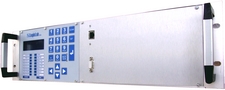
EAC DV938 device was designed to satisfy ENEL and TERNA’s requirements for automatic load shedding program in power system distribution. The device realize the under frequency load shedding function (UFLS) and under voltage load shedding function (UVLS). DV938 is a last generation digital device powered by RTEMS Real Time operating system. Device is equipped with two serial interfaces, one in front and one on the back, either RS232 or RS485 (factory customer selectable), an ethernet 10/100BASE-TX frontal interface and an ethernet optical 100BASE-FX back interface with SC connector. Different options are also available such as a second 10/100BASE-TX back interface, optical interface with ST connector, etc.. An easy to use human-machine interface allows operator to connect directly to DV938; immediate information about device status are given through LED. DV938 has four analog input voltage channels software configurable. Remote signalizing is made possible by 15 digital output relays and 4 current loop transmitter (4÷20mA, ±5mA). Inside DV938 you find
DV938 works in two ways: the first one uses only one analog voltage input, the second one uses three voltage inputs selected from two different group of three phase voltage. The group can be selected from digital input state. To prevent incorrect trip, three kinds of stop protections are available:
Field connection is achieved through two 50 poles rectangular connectors. DV938 is supplied of two software programs: the first one allowing parameterization and field monitoring, the second one to analyze fault recording (voltage, rate-voltage, frequency, rate-frequency, etc.) of each trip. DV938EAC is installed in italian substations and work to satisfy TERNA load shedding program.
|
||||||||||||
Automatic Load Shed - Documentation |
|
|||||||||||
|
User guide (Italian version)
If the English version is not available, contact us and we will provide the document that you have requested.
To download from
the website the User Guide it is necessary to have a user name and
password.
|
||||||||||||
Automatic Load Shed - Hardware technical data |
|
|||||||||||
|
Power Supply Power supply voltage: 110V DC ± 20% Medium power: 20W Voltage dips and short interruptions Insensitive to 100% of Vaux for 50 ms (min) Insensitive to 50% of Vaux for 100ms (min)
Dimensions Height: 3U Width: 19” Depth: 34cm
Voltage inputs 4 isolated voltage input channels - 6 inputs on 3 voltage channels with fullscale 100V (M2) - 1 inputs on 1 voltage channel with fullscale 400V (M1) Dielectric strength 3000V DC (1 min) Rated Voltage (Vn) M1: 57Vrms 100Vrms 400Vrms Rated Voltage (Vn) M2: 57Vrms 100Vrms Operating range: 0.01 ÷ 1.6 Vn Rated voltage selection (Vn): software Frequency Range: 10 ÷ 130 Hz Permanent overload capability: 1.5 Vn Transient overload capability - not measurable(<10s): 2Vn Power dissipation: <1VA @Vn = 400V <0,1VA @Vn = 100V Accuracy: - RMS value: ±0,001 Vn - Voltage rate: ±0,002 Vn/S - Frequency: ±0,002 Hz @ Vn <0,01 Hz @ V>0,3VnVn <0,02 Hz @ V<0,3Vn - Frequency rate: ±0,002 Hz/s
Alarms (digital outputs) 15 Relays - Out of order - 81/81R Threshold 1 - 81/81R Threshold 2 - 81/81R Threshold 3 - 81/81R Threshold 4 - 27/59/27R Threshold 1 - 27/59/27R Threshold 2 - Stop threshold Min/Max voltage and/or voltage imbalance - Stop threshold maximum frequency difference - 27/59/27R/81/81R Threshold 1 - 27/59/27R/81/81R Threshold 2 - 81/81R Threshold 3 and/or 4 - General alarm - Relay available on connector C1 - Relay available on connector C2 Dielectric strength 3300V DC (1 min) Rated voltage: 110V Rated current: 5A Maximum Switching Capacity (L/R=40ms): 0,5A @110V Endurance (mechanical): ≥107
Digital inputs 2 isolated inputs - Input signal close status HV switch (Red line) - Input signal close status HV switch (Green line) Dielectric strength 33000V DC (1 min) Threshold voltage: 60V ± 10% Input Voltage (max): 140V Time resolution: 1 ms
Current outputs 4 current loop transmitters Dielectric strength 33000V DC (1 min) Current range: 4-20mA or ±5mA software selectable Accuracy: <0,5% Transient: <200ms Maximum load: <2KΩ @ ±5mA <1KΩ @ 4÷20mA
Communication HMI with 4 lines display and keypad 16 LED Local and remote interface Ethernet 10/100 BASE-TX with auto MDI/MDI-X Ethernet 100BASE-FX (SC) - optical link Configurable as knot of a net LAN/WAN 1 RS232 front side (19.200 baud fixed) 1 RS232 back side (up to 115.200 baud) Remote connection with analog modem (not included) Isolated comunication port (Ethernet: 1500Vrms – Serials: 2500 Vrms) Field connection with 50 pins rectangular connectors
Customizing Power Supply with different input voltage Different full-scales on voltage inputs on client demand Up to 6 digital inputs available for custom application 24V digital input with threshold 18V ± 10% Custom range for current outputs HMI multi functions Additional Ethernet port 10/100BASE-TX backside ST connector for ethernet 100BASE-FX optical link Configuration parameters and thresholds are modifiable at the request within the limits of the device Integrated WebServer for parameterization with Internet Browser FTPserver for record download Different range for recording time AC digital input Optional relay outputs Different logical assignments to alarm
Standards and specifications compliance IEC 61000 – 4 – 2 (Level 3) IEC 61000 – 4 – 3 (Level 3) IEC 61000 – 4 – 4 (Level 3) IEC 61000 – 4 – 5 (Level 4) IEC 61000 – 4 – 6 (Level 3) IEC 61000 – 4 – 8 (Level 5) IEC 61000 – 4 – 10 (Level 3) IEC 61000 – 4 – 12 (Level 3) IEC 61000 – 4 – 16 (Level 4) IEC 61000 – 4 – 17 (Level 3) IEC 61000 – 4 – 29 (Level 3) ENEL DV938 ENEL REMC01 ENEL REMC02 ENEL RMEC01 ENEL RCLI01 CEI 45-5 CEI 70-1 IP30 (front) IP20 (case) COMTRADE standard IEEE Std C37.111-1991 |
||||||||||||
Automatic Load Shed - Software technical data |
|
|||||||||||
|
Parameterization and device management software SpyEAC Communication interface selection (RS232, UDP, TCP, modem setup) Software access configuration and folder management Voltage input full scales setup Device, Substation, voltage input labelling Full TCP/IP Ethernet configuration parameters Backside RS232 throughput configuration Operating mode selection (M1/M2) Trip and stop protection threshold setup Output current setup Digital input, relay output, protection status Recording time setup (Pre-trigger time, fault time, post-fault time) Memory configuration setup (circular buffer or full-fill buffer) Recording extension setup (disable, on fault time, on post-fault time) Self-diagnostic device state Reset and trigger command from PC Realtime viewing tools (analog and measure waveform, rms measure, statistic) Automatic download scheduler Firmware update wizard Recording management (Id, Date and time, Length, Trigger condition with user label) Easy-To-Use Recording management (single, selected, all recordings) Device parameterization file management tools (off-line editing, default file, download file)
Threshold M1 mode Trip threshold - frequency (ANSI 81) Threshold available: 4 Range: 45÷55Hz @50Hz rated frequency - 55÷65Hz @60Hz rated frequency Step: 50mHz Enable: included/excluded Periods of measurement: 4÷16 Periods selection: software Trip delay time: ≤100ms User trip delay time: 0,1÷60s Step: 50ms
Trip threshold - Frequency rate (ANSI 81R) Threshold available: 4 Range: -5Hz/s ÷ +5Hz/s Step: 100mHz/s Logical operator with 81: AND/OR Enable: included/excluded Periods of measurement: 4÷16 Periods selection: software Trip delay time: ≤250ms User trip delay time: 0,1÷60s Step: 50ms
Stop threshold - Min/Max voltage Threshold available: 3 Range: 0,1÷1,4Vn Step: 0,01Vn Enable: included/excluded Min/Max selection: software Stop delay time: ≤50ms User hold time: 0,1÷60s Step: 50ms
Threshold M2 mode Trip threshold - frequency (ANSI 81) Threshold available: 4 Range: 45÷55Hz @50Hz rated frequency - 55÷65Hz @60Hz rated frequency Step: 50mHz Enable: included/excluded Periods of measurement: 4÷16 Periods selection: software Trip delay time: ≤100ms User trip delay time: 0,1÷60s Step: 50ms
Trip threshold - Frequency rate (ANSI 81R) Threshold available: 4 Range: -5Hz/s ÷ +5Hz/s Step: 100mHz/s Logical operator with 81: AND/OR Enable: included/excluded Periods of measurement: 4÷16 Periods selection: software Trip delay time: ≤250ms User trip delay time: 0,1÷60s Step: 50ms
Trip threshold - Voltage (ANSI 27/59) Threshold available: 2 Range: 0,5÷1Vn Step: 0,01Vn Enable: included/excluded Trip delay time: ≤50ms User trip delay time: 0,1÷60s Step: 50ms
Trip threshold - Voltage rate (ANSI 27R) Threshold available: 2 Range: -0,2V/s ÷ +0,2V/s Step: 0,0005Vn/s Logical operator with 27: AND/OR Enable: included/excluded Time of measurement: 80÷200ms Time setup: software Trip delay time: ≤120ms User trip delay time: 0,1÷60s Step: 50ms
Stop threshold - Min/Max voltage Threshold available: 3 Range: 0,1÷1,4Vn Step: 0,01Vn Enable: included/excluded Min/Max selection: software Stop delay time: ≤50ms User hold time: 0,1÷60s Step: 50ms
Stop threshold - Voltage imbalance β = max[(V4 – μ), (V8 – μ), (V12 – μ)] / μ with μ = (V4 + V8 + V12) / 3 Threshold available: 1 Range: 0,05÷1 Step: 0,05 Enable: included/excluded Stop delay time: ≤50ms User hold time: 0,1÷60s Step: 50ms
Stop threshold - Maximum frequency difference γ = max[(fV4 – fV8), (fV8 – fV12), (fV12 – fV4)] Threshold available: 1 Range: 10÷100mHz Step: 10mHz Enable: inclusa/esclusa Stop delay time: ≤100ms User hold time: 0,1÷60s Step: 50ms
Recordings analysis software LogOscilloEAC Waveform selection wizard with colours assignment Automatic selection filters for analog and digital inputs Decimation value for waveform preview Dual time cursor Time and amplitude value in time cursor position Cursor time difference Time and amplitude value in mouse cursor position Windows and vertical zoom tool Drag-and-Drop capability for waveform overlapping Signal processing and rms waveform visualization Signal processing and true rms waveform visualization Signal processing and spectrum visualization Spectrum analysis with THD Waveform export tool for image (JPG, BMP, MetaFile, PCX, PostScript, SVG) Waveform export tool for Acrobat Reader (pdf) Waveform export in COMTRADE format Samples waveform export tool for Excel |
||||||||||||
Automatic Load Shed - Multimedia |
|
|||||||||||
Automatic Load Shed - Download |
|
|||||||||||
|
SpyEAC (Italian version) LogOscilloEAC (Italian version)
If the English version is not available, contact us and we will provide the software that you have requested.
To download
from the website it is necessary to have a user name and password. |
||||||||||||
|
|
||||||||||||
|
© LogicLab s.r.l. - VAT 13218590159 - Via della valle 67 - 20841 Carate Brianza (MB) - Italy - Tel (+39) 0362.805287 - Fax (+39) 0362.1914102 - info@logiclab.it |
||||||||||||
|
|
|||||||||||